
At a Glance
- Subsurface utility mapping combines ground penetrating radar (GPR), electromagnetic locating, and vacuum excavation to produce verified, georeferenced maps of underground infrastructure before excavation begins.
- Utility mapping is a retrieval-stage deliverable, not just a safety checkbox. Crews get scaled plan drawings, 3D models, and field-marked layouts they can act on immediately.
- Unlocated or mislocated utilities are among the leading causes of costly rework, project delays, and utility strikes. Mapping addresses all three.
- ASCE 38-22 defines four Quality Levels (QL-D through QL-A) for subsurface utility engineering. Higher quality levels require physical verification, which is what distinguishes professional SUE services from simple record review.
- Mapping integrates directly into phasing, sequencing, and subcontractor coordination, reducing last-minute conflicts during cuts, boring, and deep excavation.
- GPR mapping works on concrete, asphalt, and open soil, making it applicable across site types from urban street cuts to greenfield development.
What "Utility Mapping" Actually Means on a Construction Site
Utility mapping is a planning and risk management tool. The value of the deliverable is directly proportional to the rigor of the investigation method.
Utility mapping is the process of identifying, locating, and documenting the position of underground utilities before excavation, demolition, or construction activity begins. In practice, that means combining multiple detection technologies with field verification and translating the findings into a deliverable format the project team can use: scaled drawings, georeferenced data files, or physical surface markings that show where gas lines, water mains, electrical conduits, telecommunications infrastructure, and drainage systems are buried.
The term covers a spectrum of rigor. At the lowest end, a utility map might be assembled from as-built records and utility owner mark-outs, which are frequently incomplete or inaccurate due to decades of undocumented repairs, relocations, and additions. At the highest end, a subsurface utility engineering (SUE) investigation combines geophysical detection with vacuum excavation to physically expose and measure utility positions, then integrates those findings into a deliverable tied to project survey control.
For construction teams, the distinction matters because the quality of the mapping determines how much confidence the field crew has when making the first cut. A map assembled from outdated records provides liability documentation. A map produced through professional subsurface utility mapping provides operational intelligence.
The Outputs: What Your Team Actually Receives
The output of a utility mapping engagement should be a usable, actionable deliverable tied to your project's coordinate system and immediately applicable to design, phasing, and field operations.
A professional subsurface utility mapping engagement produces deliverables that feed directly into project documentation, not a report that sits in a folder.
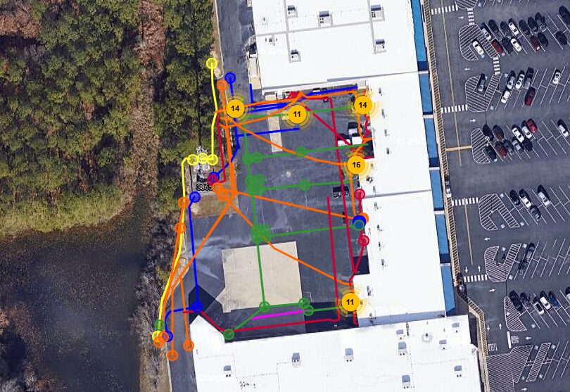
Scaled plan drawings show horizontal utility positions overlaid on the project survey base map, typically in plan view with depth annotations where physical verification was performed. These drawings can be issued in CAD format (DWG/DXF) or PDF, and they reference the project coordinate system so they align with civil drawings from day one.
GPR scan data and processed interpretations show anomalies and reflections in the subsurface profile, reviewed by trained technicians who interpret utility signatures from background noise. Raw data is often retained for QA documentation.
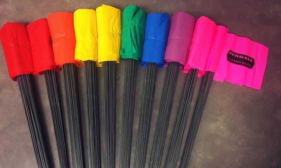
Surface markings applied using color-coded paint or flags follow APWA standards and allow field crews to visualize utility corridors directly on the ground surface. This is the format that saw operators, drill crews, and excavator operators work from in real time.
3D utility models are increasingly common on larger projects, particularly those using BIM workflows. Georeferenced utility data is integrated into the project model, allowing clash detection between proposed structures, foundations, and buried infrastructure before a single shovel moves dirt.
Depth data is the critical variable that record drawings rarely provide accurately. Where vacuum excavation or test holes are performed, actual depth measurements are incorporated into the deliverable, eliminating the guesswork that drives conservative and expensive utility avoidance buffers.
The ASCE 38-22 Quality Level Framework
Scoping the right quality level for each project zone is a cost management decision as much as a technical one. Blanket QL-A coverage is rarely necessary; targeted application is the professional standard.
Understanding quality levels is essential for scoping a subsurface utility mapping engagement correctly. ASCE 38-22 (Standard Guideline for Investigating and Documenting Existing Utilities) defines four quality levels that represent increasing degrees of accuracy and verification.
Quality Level D (QL-D) is a records review only. Utility owner records, as-builts, and permit drawings are compiled and reviewed. No field investigation is performed. QL-D is useful for early desktop screening but provides the lowest confidence for field operations.
Quality Level C (QL-C) adds a field survey of visible utility appurtenances such as manholes, valve boxes, and meters, and reconciles them with available records. Still no subsurface detection.
Quality Level B (QL-B) is where subsurface utility locating begins. Geophysical methods, primarily GPR mapping and electromagnetic locating, are applied to detect and horizontally position buried utilities. This is the most common scope for pre-construction utility mapping on commercial and infrastructure projects.
Quality Level A (QL-A) adds physical verification through vacuum excavation or test holes, providing precise three-dimensional position data for critical utilities. QL-A is required where design decisions, structural elements, or deep excavation will occur in close proximity to high-risk utilities.
Project teams should specify quality levels by zone, concentrating QL-A investigation in high-conflict areas such as proposed pile locations, deep utility crossings, and areas with known utility congestion, while applying QL-B across broader project areas.
How GPR Mapping Works in the Field
GPR mapping and electromagnetic locating are complementary technologies. Professional subsurface utility mapping engagements deploy both, with field technicians experienced enough to interpret results accurately.
Ground penetrating radar is the primary geophysical technology used in subsurface utility locating and mapping. A GPR antenna transmits electromagnetic pulses into the ground and records the reflections that return when those pulses encounter materials with different dielectric properties, including pipe walls, conduit, and the disturbed soil that surrounds buried utilities.
The antenna is moved across the survey area in a systematic grid pattern. Data is collected continuously and displayed as a radargram showing subsurface reflections at depth. Trained technicians interpret hyperbolic reflection signatures characteristic of cylindrical utilities and distinguish them from geological features, reinforcement, and interference.
GPR works through concrete, asphalt, and native soil. It is particularly effective for detecting non-conductive utilities such as plastic pipe and fiber conduit that electromagnetic locating cannot identify through induction. On concrete surfaces, GPR also detects rebar and post-tensioning cables, a critical capability for concrete cutting scopes.
Electromagnetic locating complements GPR by applying a signal directly to conductive utilities through physical connection or inductive coupling. The signal is then traced from the surface, providing high positional accuracy for metallic utilities where a connection point can be established.
The combination of both methods is the professional standard for underground utility mapping because each technology addresses the other's blind spots.
Timing and Logistics
Utility mapping is most cost-effective as a pre-design or pre-construction investment. The later in the project sequence it is commissioned, the narrower the window to act on what it finds.
The highest-value window for utility mapping is during design development, when there is still time to adjust alignments, relocate utilities proactively, and sequence work to avoid high-conflict zones. Mapping at this stage informs the design rather than reacting to it.
The second-highest-value window is during pre-construction, before subcontractors mobilize and before excavation begins. At this stage, mapping deliverables drive subcontractor coordination meetings, establish no-dig zones, and inform the shoring and dewatering design for deep excavation.
Mapping requested reactively, after a utility conflict is discovered during excavation, costs many times more than proactive mapping because the project is already stopped. Emergency utility locating can be mobilized, but it cannot recover the schedule time already lost.
For phasing and sequencing specifically, mapping deliverables allow project managers to phase excavation work around utility corridors rather than through them. Areas with high utility density can be scheduled for hand dig or vacuum excavation. Boring and HDD alignments can be designed with verified utility positions rather than record drawings alone. Pile layout can be adjusted to clear identified utilities before the drilling subcontractor mobilizes.
The Cost of Not Mapping: Utility Strikes, Rework, and Project Delays
The ROI on utility mapping is calculated against the cost of utility strikes, rework, and delay, not against the cost of doing nothing. On most projects, the calculus is straightforward.
The Common Ground Alliance publishes annual data on excavation damage in the United States. Utility strikes cause service outages, environmental releases, project shutdowns, and in cases involving gas or electrical infrastructure, fatalities. Beyond the safety dimension, a single utility strike on a congested urban site can trigger a cascade of consequences: the utility must be repaired by the utility owner on their timeline, not the contractor's. The excavation area is typically placed off-limits pending investigation. Subcontractors already mobilized absorb standby costs. Schedule float that took months to build disappears in hours.
Rework costs from utility conflicts extend beyond strike events. Crews that discover an unmarked utility mid-excavation face decisions with no good options: work around it with improvised methods, stop and wait for locating, or remove and reinstall the conflicting utility. None of these are in the original budget.
Utility mapping quantifies and manages this risk rather than accepting it. The investment in professional subsurface utility locating and mapping is a fraction of the cost of a single significant utility conflict on most project types.
Penhall's Subsurface Utility Mapping Capabilities
Penhall delivers subsurface utility mapping and locating services across the United States, supporting owners, general contractors, engineers, and utility owners on projects ranging from urban infrastructure rehabilitation to large-scale site development.
Penhall's utility mapping crews combine GPR scanning, electromagnetic locating, and field interpretation to produce deliverables that meet project requirements from early planning through construction support. Where physical verification is required, Penhall integrates vacuum excavation capabilities to support QL-A investigation in critical zones.
Deliverables are produced in the formats project teams use, including CAD drawings, georeferenced data, and BIM-compatible formats. Field crews apply APWA color-coded surface markings coordinated with plan deliverables, so the documentation and the field layout tell the same story.
Penhall has the national footprint to support multi-site programs and the field experience to work efficiently in the complex, congested utility environments common to urban construction, transportation infrastructure, and industrial facility projects.